3.2.9 Connectable
A connectable is a special kind of symbol element that defines
an outline around the symbol that the incoming role lines connect to. Normally
connectables are not shown as part of the symbol in the editors, but in the
Diagram Editor they are shown briefly during the relationship creation, marking
the connection possibilities on the objects.
A connectable consists of two parts: a target point and an
optional connectable outline. The target point is the position which the role
lines connecting to the symbol aim towards. The target point is shown as a red
circle with a cross hair. The connectable outline is displayed as a red polyline
around the target point. Role lines stop where they intersect the connectable
outline. If no connectable outline is defined, the role lines stop at the target
point. Such point connectables are mostly used in Relationship symbols that only
have text elements, as then all role lines meet in the middle of the
relationship.
Creating Connectables
There are four ways to create connectables:
 | a
default connectable is automatically created on Save if none is
defined; |
| a
connectable can be created to follow the outline of a selected element with
Duplicate
as; |
| a
connectable can be defined manually with an edge defining where roles
stop; |
| a
point connectable can be defined manually with no
edge. |
Firstly, as each object or relationship
symbol must have exactly one default connectable, if there is none when a symbol
is saved then one will be automatically added. If it is the only connectable, it
will be a rectangle enclosing the whole symbol; if there are other connectables
with ports, it will be a point connectable.
Secondly, often you will want a connectable to fit around
a certain symbol element, more accurately than the default rectangle would e.g.
around a circle. To do this select the element and choose Duplicate as |
Connectable from its pop-up menu. This will create a connectable with an
outline that fits around the selected symbol element.
Thirdly, to manually create a connectable with an
outline:
| 1) | Press
the Connectable button in the
toolbar. |
| 2) | Define
the connectable outline. This is done in the same way as creating polyline
elements: click where you want to start the polyline, add breakpoints by
clicking at suitable positions, and complete the creation of the outline by
double-clicking the left mouse button. You will normally want to check
Closed from the Connectable’s pop-up menu. For more information
about drawing polylines, see Section 3.2.5. |
| 3) | When
the connectable outline has been completed, the target point for the connectable
is added automatically at the center of the area occupied by the outline
polyline. |
Fourthly, to create a point
connectable
, i.e. a connectable without an
outline:
| 1) | Press
the Point Connectable button in the
toolbar. |
| 2) | Click
in the desired position in the drawing area. The target point will appear at the
cursor position. |
Editing Connectables
Editing a connectable is also a little different from other
symbol elements. To select a connectable, you have to click the left mouse
button exactly on top of the target point. To move the target point and the
outline, first make sure that the connectable is not selected, then press and
hold down the left mouse button on top of the target point and drag the
connectable to the new location. If you want to move only the target point,
select the connectable first, then press and hold down the left mouse button on
top of the target point and drag the target point into the new position. The
target point moves, but the outline polyline remains in the original position.
It is also possible to move or resize the connectable by changing the settings
on the Position and Size tab in the Connectable’s Format
Dialog.
For other editing purposes, Connectables follow the
behavior of polyline elements. You can make a connectable open or closed by
toggling the
Closed menu item in its pop-up menu. To edit individual
breakpoints of the outline polyline, select
Edit Points from the pop-up
menu. For more information about these commands, see Section
3.2.5.
Target points
The target point of the default connectable is used as the
center of objects or relationships when positioning them in a Diagram Editor.
For instance, when an object is aligned to a grid, the target point of the
default connectable is placed on a grid point. Similarly, when a relationship is
straightened, the target point of its connectable is placed at the intersection
of its role lines.
On the
Connectable tab (as shown in
Figure 3–13) in the Format Dialog
for Connectables, it is also possible to set two behavioral aspects of target
points. The first one is the
Sticky targetpoint setting, which controls
what happens when the mouse cursor is brought on top of the connectable during
the relationship creation in Symbol Editor.
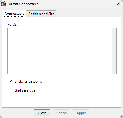
Figure 3–13. Connectable tab in Format Dialog.
| With
a sticky target point (the default), the role line is locked immediately into
the target point and remains there as long as the cursor is on top of the
connectable. This is how most symbols work: after creation, the role points
towards the connectable’s target point.
|
| A
non-sticky target point allows the end of the role line to move freely away from
the target point within the area of the connectable during creation, making it
possible to position it more freely. This is how the main object symbols work in
Sequence Diagrams: the roles are initially created pointing to where the user
clicked in the object, rather than the connectable’s target
point. |
| The
other aspect, Grid sensitive, defines whether or not the grid setting is
taken into account while connecting to a connectable with a non-sticky target
point. |


