5.2 Adding representational precision with ports
Objects, relationships and roles are strong mechanisms for
presenting the semantics between various model elements. However, sometimes even
more precise semantics or behavioral rules are required for bindings. For this
purpose, the GOPPRR metamodeling language defines a concept of Port. Port
is a concept that can be thought of as part of an object to which roles connect.
Using ports we can provide additional information or constraints on how roles
and objects are connected.
While ports are mostly intended for use on the conceptual
level, they can also be utilized for advanced representational structures. For
example, one visualization-related requirement for our Family Tree language
could be that each
Child role must be connected only to the top edge of
the ‘Person’ symbol and each
Parent role only to the side
edge (right for Male, left for Female). This would constrain users to draw
diagrams in the way we did in
Figure 1-1,
with the father on the left and mother on the right, a line between them as
parents, and from the midpoint of that line descending lines to children. With
our current binding definition such precision is not possible, so let us see
what kinds of additions would make it possible.
What we need to do is to define two new connectables for
our symbols and give them respective
Parent and
Child ports. First
of all, though, we must define a new port type. Start the Port Tool by clicking
Port Tool toolbar button or selecting
Metamodel | Port Tool. Enter
‘Family Port’ in the top-most field and add a new property type
called ‘Port type’ (with data type of String and widget of Input
Field). The Port Tool should now look like in
Figure 5-8. Accept the generation of the new
port type and quit the Port Tool by pressing
Save and Close.
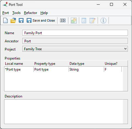
Figure 5-8. Port Tool.
Open an Object Tool then the Symbol
Editor for the ‘Male’ object. To make the drawing of new
connectables easier, remove the default one by selecting it (click the red
cross-hair in the middle of the symbol) and choosing
Delete from its
pop-up menu. You can also make life easier by setting a 5x5 grid with
View |
Choose Grid.... Activate the Connectable tool from the toolbar (the red
polygon with a cross-hair in it on the right). Move the cursor over the left end
of the straight part of the top edge of the symbol, click the left mouse button,
move the cursor to the right end of the top edge and double-click the left mouse
button. A new connectable should now appear as in
Figure 5-9 (blue parts of the symbol are
shown faded in the figure to emphasize the new connectable).
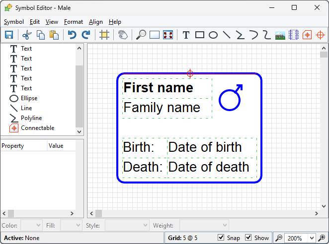
Figure 5-9. Creating a new connectable.
Keep the new
connectable selected, right-click its cross-hair and select
Format...
from the pop-up menu. In the Port(s) list, press the right mouse button and
select
Add... from the pop-up menu that opens. Enter ‘Child’
in the
Port type field and press
OK. The
Child port now
appears in the
Port(s) list as in
Figure 5-10. Press
OK to accept and
close the format dialog.
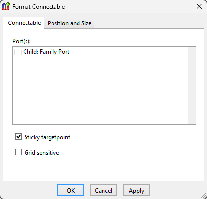
Figure 5-10. Attaching a port to the connectable.
Now
create another connectable in a similar manner for the right edge of the symbol.
Give the new connectable a new Family Port called
Parent. The symbol
definition should now look like
Figure
5-11. Save the symbol and quit the Symbol Editor.
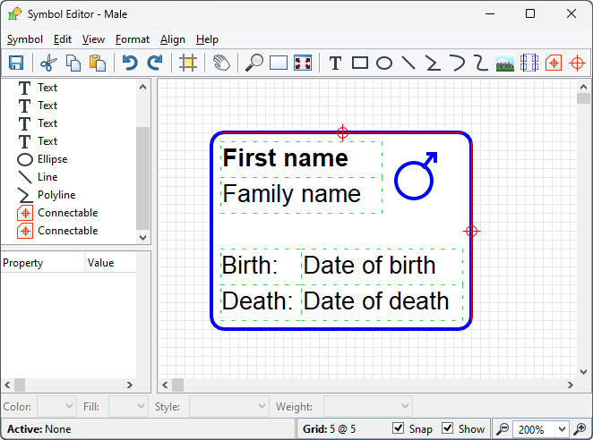
Figure 5-11. ‘Male’ symbol with two connectables.
Next,
open the Symbol Editor for the ‘Female’ object. Delete the existing
connectable, and create a new one along the top edge as you did for the
‘Male’ symbol, but do not create a new port for it. Instead, add the
existing
Child port to it by selecting
Add Existing... from the
Port(s) list’s pop-up menu in the connectable format dialog and
choose the existing
Child port from the list that opens. Next, make a new
connectable down the side like for Male, but this time along the left edge of
the symbol, and give it the existing
Parent port. It is important to use
the existing ports rather than creating new ones: otherwise you will not be able
to create relationships between these objects. The symbol for the
‘Female’ object should now look like
Figure 5-12 (again, the red symbol elements
have been faded).
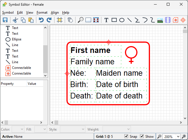
Figure 5-12. ‘Female’ symbol with two connectables.
Once
you have made these additions to the symbols, open the Graph Tool for the
‘Family Tree’ graph type and go to the Bindings page. Select the
Family relationship from the Relationships list and the first
Parent role from the Roles list, go to the Ports list,
press the right mouse button and select Add... from the pop-up menu. You
will now see the following dialog:
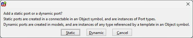
Figure 5-13. Choosing static port.
As we created static
ports in this case, choose
Static. In the list dialog that opens next,
double-click the ‘Family Port’ type and then select its instance,
‘Parent’ from the next list dialog that appears. The Graph Tool
should now appear as in
Figure
5-14.
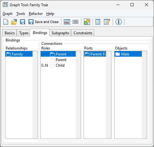
Figure 5-14. Graph bindings definer with port definition.
Similarly,
select the second Parent role and add the Parent port for it, then
select the Child role and add the Child port. Accept the changes
to the bindings by pressing Save in the Graph Tool, and you can then
close it.
Now let’s try out this latest version of the Family
Tree modeling language. Delete the objects you created before, and recreate them
as in
Figure 5-15. Note that when
clicking an object while creating a relationship, that port is selected whose
connectable’s cross-hair is closest to the cursor. To make sure that the
correct port is selected, you should thus click near to the edge you want: the
right edge for a father, left for a mother, and top for a child. You will notice
that unlike before, when role lines could move freely around the symbol while
you moved related objects, all
Child roles now remain connected to the
top edge of the symbols. Similarly,
Parent roles stick to the left or
right edge of the parent symbols.
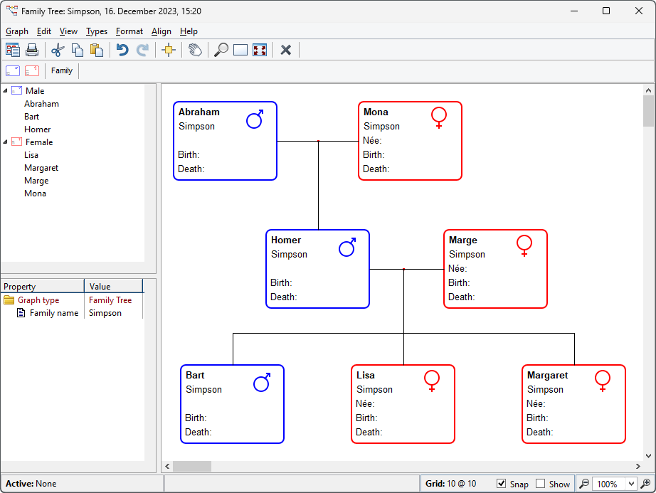
Figure 5-15. Family Tree with ports.
If you notice that
although you are using the grid, role lines are no longer precisely horizontal
or vertical, the probable cause is the position of the connectables’
cross-hairs. These form the target points to which role lines point. If, for
example, the Child cross-hair is not directly above the default
connectable’s cross-hair in the middle of the symbol, role lines to the
Child port will not be exactly vertical. You can correct the position of the
cross-hairs in the Symbol Editor. Select the cross-hair at the centre of the
symbol, and with the shift key down click the cross-hair for the Child
connectable to select that too. Then choose Align | Align Center to shift
the Child connectable along so it is centered over the default
connectable’s cross-hair. The Parent connectable can be corrected
similarly, but using Align | Align Middle to shift it up or
down.


