3.2.9 Template
Template symbol elements offer a powerful way to construct
symbols using pre-defined subsymbols that are fetched dynamically and displayed
as part of the hosting symbol. These subsymbols can also act as dynamic ports
for more precise role-and-object connection semantics, in a similar fashion to
the existing static ports.
Basically, templates provide a set of subsymbol slots that
are distributed along a template path in a user-definable order and intervals.
When filling the slots, the template will first retrieve a set of objects to be
allocated to the template. There are several possible sources for these
subobjects: a single property, a collection property, a subgraph or a generator.
Each subobject will provide a subsymbol to be displayed in its slot. A subsymbol
can be the subobject type’s symbol or it can be retrieved from the symbol
library. In addition to being represented within the slots by their subsymbols,
the subobjects can be also revealed as dynamics ports that roles can connect to
according to the binding rules.
Creating templates
A template is created by drawing the template path first and
then defining the other settings from how and where the subsymbols are to be
fetched and distributed along the path.
To create a template:
| 1) | Press
the Template button in the
toolbar. |
| 2) | Click
the cursor in the drawing area where you want the template path to begin. This
places the first point for the path. You can cancel the creation at any time by
pressing the right mouse
button. |
| 3) | Add
new breakpoints by clicking in the desired
positions. |
| 4) | Complete
the creation by double-clicking the left mouse button for the end of the last
line segment. If you double-click on or near the first point, the path will be
closed; otherwise it will be open. |
Once
the path definition has been completed, the template will appear as blue dotted
line and have the subsymbol slots positioned according to the default
distribution as in
Figure
3–12.
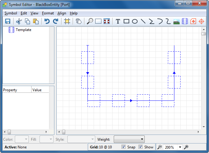
Figure 3–12. Newly created template.
Editing templates
A template path’s breakpoint operations are the same as
for a polyline, so for information about them, please refer to Chapter
3–11. To edit the layout (i.e. the slot geometry and how they are
distributed along the path) select
Edit Layout from the template’s
popup menu. Enabling the editing mode will bring the focus on the first
subsymbol slot with selection handles and two additional tool handles as shown
in
Figure 3–13.
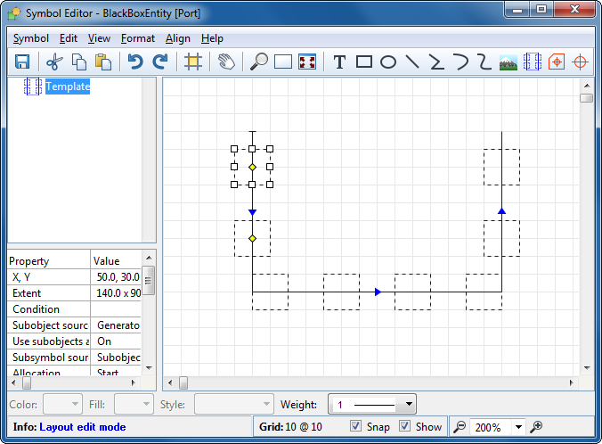
Figure 3–13. Template layout editing mode.
The white
selection handles manipulate the size and geometry of the subsymbol slot, and
the yellow distance handles control the distance before the first slot, and the
interval between the slots (if a mid-out allocation has been chose, the start
distance handle will be inactive). By default the slot is center aligned:
centered around the allocation points, the first two of which are shown by the
distance handles. You can change the alignment by placing the cursor within the
slot box, pressing and holding down the left mouse button and dragging the slot
around then allocation point. By default the slot alignment snaps so either an
edge or the center is on the allocation point; hold down the Ctrl-key to move
the alignment more freely..
 | Please
note that subsymbol slot’s offset from the allocation point is relative to
the direction of the template path. As the layout remains the same for all path
segments, this means that the absolute position of the slot may be different on
different segments, as shown in Figure
3–14. Rather than all being absolutely to the left of the line, as on
the first segment, the slots in the figure are aligned to the
‘outside’ of the line – actually to the right of the line as
we imagine moving along it in the direction of the arrows.
|
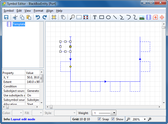
Figure 3–14. Subsymbol slot offsets.
It is worth
noting that the template layout shown in the Symbol Editor is only a preview
based on the assumption that a maximum number of subobjects have been found. It
is possible that that not all previewed slots are filled or that there are not
enough slots for all subobjects in the Diagram Editor. If the symbol’s and
subsymbol slot’s scalability settings allow, it is possible to reveal more
slots by scaling the object in Diagram Editor.
Templates can also cover area and grid-like layouts by
cloning the template path. Basically this means that the entire path is cloned
and repeated multiple times. The position and spacing of each clone is specified
along a cloning path, in a similar fashion as the subsymbol slots are
distributed along the template path. The cloning can be activated by selecting
Cloning from the template’s popup menu. This will toggle on the
clone path, shown as green path segment, and initially created perpendicular to
the template path (as in
Figure
3–15).
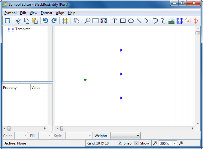
Figure 3–15. Clone path.
The clone path can be edited
in the same way as the template path by selecting popup menu command
Edit
Points for breakpoint editing or
Edit Layout for layout editing.
Breakpoint editing follows the same procedures as with polylines, but handles
are shown both for the cloning path and for the template path. For the layout
editing, the control handles for the template path remains the same as
previously but there are now two new yellow control handles for the clone path:
distance from the start and interval (as shown in
Figure 3–16).
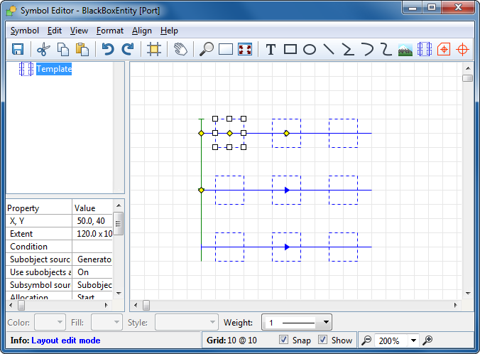
Figure 3–16. Editing clone path.
The layout specific
settings are also available in the template’s Format dialog’s
Template Layout Settings tab.
Template subobject settings
The source for subobjects is defined on the Subobjects page in
the template’s Format dialog (shown in
Figure 3–17).
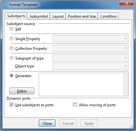
Figure 3–17. Template subobject settings.
There are
five different source options:
 | Self:
use the hosting object itself as a subobject (useful for showing a library
symbol as part of several
symbols). |
| Single
Property: use the object from a single property in the host
object. |
| Collection
Property: use the objects from a collection property in the host
object. |
| Subgraph
of type and Object type: from the host object’s subgraph of the
specified type, use the objects of the specified type.
|
| Generator:
use a set of objects retrieved by a generator. The generator must output the
objects one per line, and the template will pick up the first Live Code
hyperlinked object on each line. For more information about defining generators,
please refer to Chapter 5. |
In
addition to the subobject source it is also possible to define here whether the
subobjects will be used as dynamic ports when creating bindings, with the
Use
subobjects as ports check-box. Checking the box will allow each
subobject’s default connectable to be revealed as a port, which will
behave in accordance with that connectable’s
Sticky targetpoint and
Grid sensitive settings. If the check box is left unchecked, plain
subobjects will be displayed without the port behavior. By default, the dynamic
ports are unmovable. Checking the
Allow moving of ports box will allow
the user to drag the ports along the template
line.
Template subsymbol settings
In order to be able to be displayed, the subobject needs to
have visualization – either its own symbol or one from the Symbol Library.
The subsymbol source can be defined on the Subsymbol page in the
template’s Format dialog (shown in
Figure 3–18).
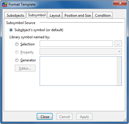
Figure 3–18. Template subsymbol settings.
To use an
object’s own default symbol, select Subobject’s symbol (or
default). To use a subsymbol from the Symbol Library you can either select
it directly or provide the name of the symbol to be fetched. To select the
symbol from the library, select the Selection radio button and press the
... button to open the Symbol Browser for choosing the subsymbol.
Alternatively, the name for the library symbol can be provided from a property
(select the Property radio button and choose the property from the
pull-down list) or a generator (select the Generator radio button and
define the generator that outputs the name).
| For
more information about the Symbol Library and Symbol Browser, refer to Section
3.6. |
Template layout settings
The Layout page in the template’s Format dialog (as
shown in
Figure 3–19) gathers
the settings needed for defining the actual layout for the subsymbol
distribution along the template path.
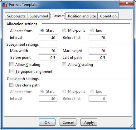
Figure 3–19. Template layout settings.
In the Layout
page, the topmost section, Allocation settings, defines how subsymbol
slots are positioned on the path:
| Where
to Allocate from, i.e. shall we start distribution from the beginning,
middle or end of the template path (in the mid-point case we spread from the
middle
outwards) |
| Interval,
i.e. the distance between the slots, measured along the
path |
| Before
first, i.e. the distance from allocation start to the first
slot |
The middle section contains the settings
for the subsymbol slot:
| Max.
width and Max. height: the width and height of the slot area. This
must be big enough to contain the largest subsymbol one of these slots will
display, placed according to the alignment settings. Parts of the subsymbol
outside the slot will be clipped from display. Note that the template’s
Weight may be used to prevent clipping of wide lines along the outer
edges of the subsymbol slot. E.g. if a subsymbol is a 20x20 rectangle with a
weight of 10, the outer half of the line widths would be clipped by a 20x20
subsymbol slot; increasing the template weight to 10, to match the subsymbol
rectangle, will allow the subsymbol to display fully, and remain correct even if
the subsymbol
scales. |
| Before
point and Left of path: the alignment of the subsymbol slot. The
value is the fraction of the subsymbol slot that is respectively before or to
the left of its allocated point, from the perspective of one moving along the
template path segment in the direction of its
arrowhead. |
| Allow
X and Y scaling: whether the subsymbol slot is allowed to scale with
the hosting object. If the subsymbol slot allows X scaling, then as the parent
symbol is scaled horizontally, the number of slots shown there remains constant
and each slot grows horizontally — as does the subsymbol displayed in it
(unless its symbol forbids scaling). If the subsymbol slot disallows X scaling,
then as the parent symbol is scaled horizontally, the number of slots shown
there increases, and each slot stays the same
size. |
| Targetpoint
alignment: when this is set, the subsymbol will be aligned so that its
default connectable’s target point will be in that point around which the
subsymbol slot is aligned (i.e. the first yellow
handle) |
The final section at the bottom of
the dialog is reserved for the clone path settings:
| Use
clone path: toggles cloning on or
off. |
| Allocate
from: the starting point for the distribution (the options –
beginning, middle, end – and the behavior are the same as layout’s
general Allocation
settings). |
| Interval
and Before first: similarly to the Allocation settings, the
distance between clones, and the distance from the allocation starting point to
the first clone. |
The clone path allocation
settings will be turned off when the clone path is
inactive.


