3.1 Working with the Symbol Editor
To open the Symbol Editor, press the
Symbol
button
in the corresponding Object, Relationship, or Role
Tool (in the Port Tool, the Symbol button is disabled as Ports do not have their
own symbols). You can also open the Symbol Editor for a type from almost any
place where that type is displayed in a list, by selecting Edit Symbol from the
type’s pop-up menu. In a Graph Tool’s Types tab and Bindings tab,
and in the Diagram Editor sidebar in the tree view or the top row of the
property sheet, Shift-double-clicking the type will also work.
As a result of any of the above, a Symbol Editor opens
showing the symbol of that type as in
Figure
3–1 (if no symbol has yet been defined for the type, the editor will
initially be empty).

Figure 3–1. Symbol Editor.
The Symbol Editor window
can be divided into five parts. The usual menu bar can be found from the top of
the window. Below the menu bar, there is a toolbar with action buttons for
Save, Cut, Copy, Paste, Undo, Redo and Zoom
commands (Set Zoom, Default Zoom and Zoom to Fit), as well
as the tool buttons for creating various symbol element shapes. The largest part
of the window, the drawing area that contains the symbol elements, lies in the
middle. At the bottom of the window, there is a formatting bar for symbol
element properties like color, line style and weight, and a status bar showing
information about the currently selected elements and grid and zoom
settings.
Creating a new symbol
If the Symbol Editor is opened for a type that has an existing
symbol, the symbol is automatically loaded into the editor (if there is no
existing symbol definition, the Symbol Editor will initially be empty). To clear
the editor and start with an empty symbol, select Symbol | New. Please
note that this new symbol is still attached to the currently selected
type.
Saving a symbol
To save the symbol definition, select Symbol | Save or
press the Save button in the toolbar.
Undo/redo
To undo Symbol Editor operations, select either Edit |
Undo or press the Undo toolbar button (or press Ctrl+Z). To
redo, select Edit | Redo or press Redo toolbar button (or press
Ctrl+Y).
Using the Symbol Library
Normally a symbol definition is simply saved as part of the
type it belongs to. However, there is often a need to reuse symbols or parts of
symbols between types, and therefore the Symbol Editor allows symbol definitions
to be stored in the Symbol Library of the current default project. To save the
symbol definition into the Symbol Library, select Symbol | Save to
Library... and enter the name for the symbol definition when
prompted.
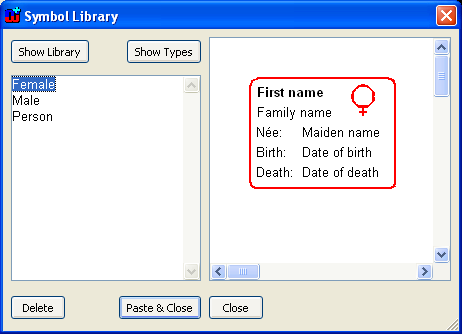
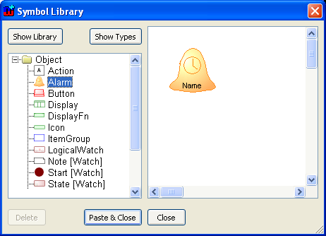
Figure 3–2. Symbol Library.
To browse, manage and
retrieve symbols in Symbol Library, select
Symbol | Browse Library....
This will open the Symbol Library Browser as shown in
Figure 3–2. It is worthy to note that
Symbol Library Browser allows browsing and retrieving of not only symbols stored
into the library but also symbols of other types loaded from the repository. By
default the browsed shows the symbols stored in the library. To view the symbol
in other types, press
Show Types button on top of the screen. This will
change the view to similar as in
Figure
3–3. To view the symbols in the library again, press
Show
Library button.
Figure 3–3. Symbol Library showing symbols in types.
Available
symbol definitions are shown in the list on the left and a preview of the
selected symbol is displayed on the right. To load the symbol definition from
the library or other type, press the Paste & Close button. This will
retrieve the symbol elements and place them on the drawing area. Please note
that this addition is non-destructive, so the symbol elements possible already
existing on the drawing area are spared. To remove the selected symbol
definition from the symbol library, press the Delete button and select
Yes in the confirmation dialog (please note that you cannot delete symbol
definition from another type this way). To exit the Symbol Library Browser,
press the Close button or close the browser window.
It is worth noting that property text fields cannot show
the names of the properties in the preview (the figure contains only fixed text
elements). When pasted, unless into the same symbol or a subtype, you must
assign the desired properties to the text fields.
Bitmap import
To import a bitmap as a symbol element, select
Symbol |
Import Bitmap... and select the bitmap file from the file dialog that opens.
Supported file types are
.bmp,
.gif,
.jpg and
.png. For more information about bitmap
symbol elements, see Section
3.2.8.
SVG export/import
The Symbol Editor provides a mechanism for exporting symbol
elements as Scalable Vector Graphics (SVG) documents and importing these
documents back to MetaEdit+. SVG is an XML notation for describing vector
graphic images. MetaEdit+ supports the SVG Tiny 1.2 profile – for more
information about this format, please refer to
www.w3.org/TR/SVGMobile12.
To export the current symbol's elements to an SVG file,
select Symbol | Export SVG.... Enter the name for the SVG file when
prompted. To import elements from an SVG document, select Symbol | Import
SVG... and select the SVG file from the file dialog that opens. If errors
are encountered during the export or import, a warning dialog will be shown
providing information about the possible cause of the error.
Exiting the Symbol Editor
To exit Symbol Editor, select
Symbol | Exit or close
the Symbol Editor window. If there are unsaved changes, a dialog as in
Figure 3–4 will be shown to prompt
whether or not to save them.
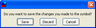
Figure 3–4. Confirmation for save on exit.
Using the grid
Using the grid helps you position and scale symbol elements
accurately. When the grid is active, elements are not moved or scaled completely
freely anymore, but with defined steps. To set the grid step, select
View |
Choose Grid... to open the grid size dialog (
Figure 3–5). In the grid size dialog
you can set the grid step values for both axes either by entering them into
their respective number fields or by using the sliders. If you want to make sure
that the grid for both axes is the same, check the
Uniform grid check
box. Pressing the
Default button will restore the default grid step
values.
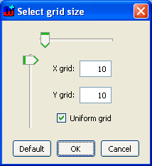
Figure 3–5. Setting grid step.
To make the grid
visible in the drawing area, select View | Show Grid or toggle it on by
checking the Show checkbox in the Grid section of the status bar
on the bottom of the window. To activate the grid, choose View | Snap to
Grid or check the respective checkbox in the status bar. Once activated, all
further element operations will conform to the grid steps. However, activating
the grid does not force symbol elements to align themselves along it. To do
this, select Align | Align to Grid: this will align the top left of the
selected elements (or all elements if none are selected) to the nearest grid
point.
Setting zoom
The Symbol Editor is opened with a 200% zoom by default. To
change the zoom, either:
| 1) | Select
View | Zoom... from the menu bar or press the Zoom button in the
toolbar. This will open a Zoom dialog (Figure
3–6). |
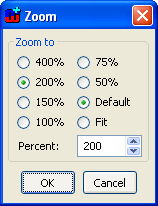
Figure 3–6. Zoom Dialog.
| 2) | In
the Zoom dialog, set the proper zoom value either by selecting from the
predefined values or by entering your own value in the Percent field.
There are also predefined settings for zooming the symbol to fill the whole
drawing area (Fit) and restoring the 200% default zoom
(Default). |
Or:
| 1) | Select
the Zoom Tool from the Symbol Editor
toolbar. |
| 2) | On
the drawing area, press and hold down the left mouse button and drag the
magnifier cursor to define the area you want to zoom to. Or, alternatively,
position the magnifier cursor on top of the element or area you want zoom closer
to and click the left mouse button. This will zoom in one
step. |
 | By
default, the Zoom Tool operates in ‘Zoom in’ mode. You can
change to ‘Zoom out’ mode by pressing and holding down the Ctrl-key
while the Zoom Tool is active. |
Or
one of the following:
 | To
set the default zoom (200%) select Default zoom from the
toolbar. |
| To
zoom to fit select Zoom to Fit from the
toolbar. |
| Select
the zoom percentage from the pull-down list on the right of the status bar.
|
| For
zooming in or out step-by-step, press the round + or –
buttons on the right of the status
bar. |
| Hold
down Alt and use your mouse scroll wheel to zoom in and
out. |
Refreshing window
To refresh the drawing area, either select
View |
Refresh from the menu or press F5.