Writing generators for graphs with decompositions
Printed From: MetaCase
Category:
Forum Name: MetaEdit+
Forum Description: All topics relating to MetaEdit+ or DSM
URL: https://www.metacase.com/forums/forum_posts.asp?TID=252
Printed Date: 27.Mar.2026 at 02:14
Software Version: Web Wiz Forums 12.05 - http://www.webwizforums.com
Topic: Writing generators for graphs with decompositions
Posted By: iceman
Subject: Writing generators for graphs with decompositions
Date Posted: 06.Jul.2011 at 11:33
I have written my own schema for state machine representation, but it has some semantics for the meta-modeler. Rather than a hierarchical representation of the xml nodes which can be edited , some nodes like the UI components have to be represented by another model, so that they can be separately authored. How can the xml be generated in such a case? Example of the xml is as follows:<state no="1"> |
Replies:
Posted By: jpt
Date Posted: 06.Jul.2011 at 13:21
|
Separating state machine behavior and UI is generally a good idea. In MetaEdit+ you could then have one Graph type for state machine and another for UI. There are several ways to combine these and after looking the example:
A state object type could have a property that refers to the UI components. This property type (called ‘screen components’ in XML) would be a collection that either refers to the component name (string value) or to the whole UI component object. In the former case the property type in the state object would having string data type whereas in the latter case the data type of the property would be a collection of objects containing the UI components. If you want to see an example of this, please check the digital watch example where the state object type refers to (now to one only) the display definition. In this example the display definition object (your UI component) is represented in the same graph type with the state machine but there could also be separate graph type for the display defnitions.
If you follow this latter approach and have different kind of UI component types in your language you could create them into inheritance hierarchy and refer to the supertype (e.g. ‘_general UI component’ which then have subtypes like ‘text component’, button component’ etc. The ‘_’ in ‘_general UI component’ makes the type abstract so that it can’t be selected when choosing the component in the selection lists.
Depending on your needs you may also consider having subdiagram that specifies the UI component and then there could be an explosion link from state in state machine diagram to the UI component Graph type.
To decide what works the best it would be good to have several examples. Now I would personally start with the direct reference to the object. In the generator when producing the xml from the state machine you can then access the UI component and its properties easily while navigating in the state machine.
If some of the properties of the UI component are defined in the graph type where the UI component is specified (like its connections to the other elements) you can navigate with MERL to that. The way navigation works is using the unique identifier (oid) and navigating with do graphs command to find the same object from UI component graph type.
I hope this helps.
|
Posted By: iceman
Date Posted: 06.Jul.2011 at 15:18
|
Thanks for the suggestions. The way I thought of modeling this was to have separate graphs for state machine and UI definition. Also, a problem is then to handle the complexity if there are lots of states. I could not understand when you said " direct reference to the object". is this for the first method(same graph) or the second method(separate graphs)? I was also thinking of improving my modeling concept used in the xml. Since, once there are many screens(states), it would be hard to define them even graphically using Metaedit+. What would be an output xml example from the technique you've described if there are multiple screens? |
Posted By: jpt
Date Posted: 06.Jul.2011 at 16:04
|
I think we are on the same page here looking to have two graph types keeping the design of state behavior and UI different.
By reference to the object I mean that the collection property in a state could refer to a number of screen components (like button, text). These screen components can be originally designed in the separate language (Graph type for UI definition), but only referred via the state. This would reflect to what you had as xml file for output.
Now, reading your original question again, I see that you are perhaps looking for a solution in which each state has a single subdiagram (via decomposition) containing the whole screen definition. While that works too then there is the challenge that you can’t anymore have a substate machine since the decomposition is already used. Perhaps this does not matter as the screens are defined only in the substates?
In my suggestion I followed the XML file where each state has to one screen definition, which again contains a number of components.
|
Posted By: iceman
Date Posted: 06.Jul.2011 at 16:19
|
Yep, got that part. If there is a separate graph for UI component definition, then I would need to separate the event transitions coming from some of the UI components like buttons, because state change occurs because of that as well. How to do that? I'm a bit confused when you said "explosion link from state in state machine diagram to the UI component Graph type". Is that a better design approach than having decomposition? I'm quite happy to change the xml schema to have a better design that would let tackle two things -one,the definition of UI components in another graph and second,having lots of states. |
Posted By: jpt
Date Posted: 07.Jul.2011 at 17:37
Yes, if you want to reuse the same UI component definition in many screens/states then the event part would go to the state transition diagram, most likely to the Transition relationship type (in terms of GOPPRR). This is basically like in almost any state machine where we specify the event that triggers the transition from one state to another. This transition could also have other properties if needed.
The other approach would be to move the UI definitions from model to metamodel. In other words, you would not have a modeling language to specify screens and UI components but those would be defined by the metamodeler. The S60phone shows such example if you want to look the details. While there text size, icon etc. are fixed nothing prevents to add such details to the UI element so that default setting could be overrided by entering them in the model.
In MetaEdit+ an object type, like State, can have only one decomposition target graph, whereas explosion that is semantically weaker can target several target graphs. This means that if you want to have both state hierarchy and link to screen definitions from a state you may not use only decomposition. Instead you could use explosion to target UI Graph and decomposition to sub state machine. To keep the designs still consistent there could be a report in MERL that checks that only one explosion link is defined. At the same time the checking could also report on states that do not have (yet) UI elements.
It is good if you have the possiblity to modify the XML schema but if the generator produces the XML file the structure of the metamodel can be quite different. I would thus try to define the language first that makes modeling of states and UI part fast and easy and then let the generator target whatever XML scheme is needed. |
 iceman wrote:
Posted By: iceman
Date Posted: 13.Jul.2011 at 13:32
|
Hello, Thanks for the reply. In the meantime while you answered the question, I had come with some graphical design issues. My version of the state machine editor is a customized version of a generic State machine editor, in that it has definition of UI design in some states(not all). A generic state transition diagram can be used to describe the behavior of a class, a use case or a system. While searching for a proper representation I found that a lot of the confusions arise from the way the term "FSM" is used in literature and their representation(specially state charts versus state machine). I found that a form of state transition diagram given by the IETF standards http://i52.tinypic.com/2hx7g4n.jpg - here and a more common known one from UML here ( http://i54.tinypic.com/1217n0x.jpg - link , http://i54.tinypic.com/5jveys.jpg - link ). There are other graphical representations such as SDL, BSCM etc. The UML notation in plain english converts to the following: when the specified event occurs, if the guard condition is true, perform the specified action and send the specified message. For my requirements, the xml i constructed for the domain does not exactly match the semantics of a standard state machine graphical representation, i.e the event definition is embedded in the button UI component definition. Hence, I am not able to have a better DSL design. I have the state definition according to the XML example below and constructed two graphs : one is a state transition diagram graph( http://i51.tinypic.com/b4gvac.jpg - link ) and another a UI layout graph( http://i53.tinypic.com/2vmztdz.jpg - link ). I can define the states, but since buttons are inside another graph, how can i specify the events defined by them in the state transition graph? How can I define multiple "backgroundactions" and "expectedevents" in my state transition diagram graph? If I specify them as Properties in a Relationship, I'm unable to add the "parameter" anymore Ref: There are couple of xml tags which can be confusing to understand. Their meanings are as follows: actions+backgroundactions - same as the concept of action in UML expectedevents - both asynchronous periodic(timeout)[ http://i55.tinypic.com/29m4075.jpg - link ] and asynchronous sporadic(shown as "FD" and "FE" here) received by the state. These are not from any state but from external processes and clocks. There is no concept for representation of this in UML. events - asynchronous aperiodic events(button clicks) XML example: <state no="0"> <timeout>1</timeout> <backgroundactions> <rocosmessage name="FDSessionStart" type="EVENT_MESSAGE" senderid="RCP" receiverid="NA"> <parameter type="unsigned int" name="id" vartype="text">1</parameter> </rocosmessage> </backgroundactions> <expectedevents> <event name="TimeOut"> <action preconditions="no" name="randomtransition"> <parameter> <type>state</type> <name>n</name> <value>11010</value> </parameter> <parameter> <type>state</type> <name>n</name> <value>11020</value> </parameter> </action> <savedvalues> <save value="state" tag="VARFirstScreen"/> </savedvalues> </event> </expectedevents> </state> <state no="1"> <timeout>129</timeout> <screen> <components> <video x="142" y="144" width="720" height="480" repeat="yes"> <path>Introduction_final.flv</path> </video> <button label="EXIT" width="80" height="30" x="920" y="10" textsize="14" icon="none" iconx="20" icony="20" adjtext="-5"> <event name="clicked"> <action preconditions="no" name="transition"> <parameter> <type>state</type> <name>n</name> <value>1000</value> </parameter> </action> </event> </button> <button label="MENU" width="250" height="100" x="212" y="630" textsize="40" icon="iconRight2.png" iconx="65" icony="20" adjtext="-10"> <event name="clicked"> <action preconditions="no" name="transition"> <parameter> <type>state</type> <name>n</name> <value>800</value> </parameter> </action> </event> </button> <textfield x="200" y="50" width="924" textsize="80" background="0" border="0"> <text say="0"> <part type="text">PLEASE USE ME</part> </text> </textfield> </components> </screen> <expectedevents> <event name="FD"> <action preconditions="no" name="transition"> <parameter> <type>state</type> <name>n</name> <value>98</value> </parameter> </action> </event> <event name="FE"> <action preconditions="no" name="transition"> <parameter> <type>state</type> <name>n</name> <value>9000</value> </parameter> </action>> <savedvalues> <save value="value1" tag="VARFallUser"/> <save value="value2" tag="VARAlrmType"/> <save value="value3" tag="VARLandmark"/> </savedvalues> </event> </expectedevents> </state> |
Posted By: jpt
Date Posted: 13.Jul.2011 at 15:33
|
Because of the different semantics in different domains there is also a need for different domain-specific languages, here for different state transition diagrams. If I understood correctly, one UI graph (represented as a diagram) specifies one screen which again contains one or more screen elements (e.g. button). Right?
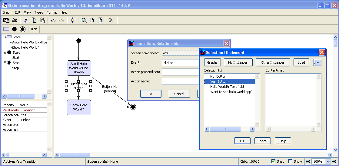
There are several possibilities but my first suggestion would be adding a new property type for the ‘Transition’ relationship type (or role types) in State Transition Diagram. This property type, called here ‘Screen component’ is of data type ‘Object’ and it contains a particular object type called ‘UI element’.
Since there are different type of screen components (text field, buttons, menus) the above structure expects that all screen components are subtypes of ‘UI element'. In this way the modeler can select which type of screen component is related to the event (e.g. a button).
The transition relationship could also include other property types, like
- Action precondition (datatype: string)
- Action name (datatype: sting)
- Parameters and additional design data as needed
For the modeler then the choices to be made would look like in the screenshot below. Here the Screen component field refers to elements defined in the UI graph and you may browse and select them via the selection tool shown in the right.
 If you can analyze the domain further you may find that actions are dependent on the type of UI element. Therefore the Event property type that is currently specified to be part of the Transition relationship type could be given instead to the button use. Then the modeler would add a UI element, like button and get only respective events (like ‘clicked’). This way he would not be able to specify ‘clicked’ e.g. for a text field.
In the same way you can have other mappings, like have a property ‘Screen’ in State object. The ‘Screen’ property type is of data type ‘Graph’ and thus refers to the UI graph containing the screen definition.
I hope this helps.
|
Posted By: iceman
Date Posted: 16.Jul.2011 at 02:27
|
Thanks for the reply.Yes, you're right. one UI graph specifies one screen which again contains one or more screen elements (e.g. button).The former is called the state editor and later the screen editor. You've answered some of the questions. I had a couple more in the last post. The state changes not only on events from screen elements, but also from external async events. The state also performs some actions. How to put these in the editor as metatypes which can be modeled while scenario authoring? The way I have defined the transition relation is http://i51.tinypic.com/2ivf96a.jpg - here . Is it correct? The other issues I faced were as follows. I added the screen graph property to the state as shown http://i55.tinypic.com/162350o.jpg - here , but the state object blocks the screen editor till I press "all ok" on the state object. http://i56.tinypic.com/33vcbyh.jpg - Is that preventable ? I also happened to get an http://i54.tinypic.com/2v33036.jpg - exception while adding graphs from the transition. |
Posted By: stevek
Date Posted: 18.Jul.2011 at 13:27
Normally, events are specified as part of a transition. Looking at your XML and the screenshot of your metamodel, I don't see transitions mentioning events - only screen elements defining events. Imagine you have a state " http://en.wikipedia.org/wiki/Red_pill_and_blue_pill - Nero's choice " with a screen with two buttons "Take red pill" and "Take blue pill", and you want the red one to go to the "Real world" state and the other to the "Matrix world" state. I'd define the button in the screen to have text "Take red pill" and trigger event "red", and then have a transition from "Nero's choice" when event "red" occurs that goes to "Real world".
When there are different kinds of events, as in your case with screen element events and async events, I prefer to have the event (or the element that causes it) directly visible in the diagram. Look at the http://www.metacase.com/support/45/manuals/watchtut/we-Preface_.html - Watch Example , e.g. http://www.metacase.com/support/45/manuals/watchtut/we-2_4.html - Figure 2-8 , where each transition is an n-ary relationship connecting a source state, a target state, and an event (a button press). You could use a similar approach, with your buttons (or the events they trigger) being directly in the diagram. You could then use async events directly in the diagram in the same way.
For actions, the Watch Example only has actions that occur during transitions, and these are represented by connecting them to the transition relationship with an extra role. If you have entry actions for a state, these could be part of the state (a collection property of Action objects), and similarly for exit actions.
I don't think so: you are allowing a Stop State to be the Source of a Transition. Normally it's: Transition (From (Start | State)) (To (State | Stop).
Sure: rather than adding the screen graph as a property to the state, add the screen graph as an explosion for a state.
Please email the meplus0.err log file from your MetaEdit+ working directory to mailto:metaedit.support@metacase.com - metaedit.support@metacase.com , and we'll take a look.
|
Posted By: iceman
Date Posted: 20.Jul.2011 at 06:07
|
Thanks for the suggestions. Adding events for transitions would be different if I do it in the Watch example way compared to what jpt suggested. In the Watch example, the Event role is connected to an object(button). However, in my case I have many different kinds of events which lead to a transition. Events from UI components and async events(10-15 kinds of). The events from UI components(only buttons currently) just happens to be present in another graph-"Screen Editor". Do I have to add a separate object for each class of events and associate then in the "Transition" relationship? Once I have defined the buttons in the Screen Editor graph, I want them to be available while I use the State editor graph to define the events for transitions. I could not find the error log file in the working directory. Is it in the c:\program Files directory? |
Posted By: stevek
Date Posted: 20.Jul.2011 at 13:38
|
The underlying need is for a transition to have the information of which event(s) trigger it. You have events coming from Screen Components and from Async sources. Juha-Pekka (jpt) suggested a property in the transition which would be a direct reference to a Screen Component, which would have been specified earlier in the subgraph of the source State. Now we have a bit more information, we see that's maybe not enough, since there needs to be a way for transitions to be caused by Async events as well as Screen Components.
One way would be my suggestion, to place the event trigger as an object directly in the diagram and connect from the Transition to it with an Event role. The event trigger objects could be Screen Components and the various Async events. I'm guessing that at least some Async events need more information, e.g. a Timeout might need the modeler to supply its duration. [Actually I see you specify the timeout duration in the state itself, but maybe some other async events need extra info themselves.] In that case it makes sense to have a separate object type for each. Perhaps you could have an abstract object type "_Async Event", with a subtype "Timeout" with a duration property, and another subtype "Simple Async Event" with a Radio Button or Fixed List property "Event Type", listing all the non-parameterizable async events (e.g. "Power Down", "Power Up").
You'd thus add some object types to your graph type (Screen Component, Timeout, Simple Async Event), and in the binding for Transition you'd add an Event role that can connect to Screen Component or _Async Event.
An alternative would be to have a different relationship type for some of the async events, e.g. a Timeout relationship that has a property "duration" and connects the source state in a "Timeout From" role to the target state in a "Timeout To" role. You could then enforce only one Timeout transition per state by a Connectivity Constraint on the "Timeout From" role.
In your XML, what is the semantics of a button event action's state parameter, in particular its <name> and <value>? They sound like they specify the state to go to when that action occurs, but the name is always 'n' and the values don't match any state names in the example XML.
The working directory is specified by the "Start in" value of the MetaEdit+ shortcut, by default My Documents\MetaEdit+ 4.5.
|
Posted By: iceman
Date Posted: 22.Jul.2011 at 08:24
|
The semantics of a button event is the following: the value specifies the state to which the transition occurs. For example, <button label="SKIP" width="200" height="200" x="412" y="500" textsize="40" icon="none" adjtext="30"> <event name="clicked"> <action preconditions="no" name="transition"> <parameter> <type>state</type> <name>n</name> <value>4192</value> </parameter> </action> </event> </button> There are timeout events, for example: <event name="TimeOut"> <action preconditions="no" name="transition"> <parameter> <type>state</type> <name>n</name> <value>4172</value> </parameter> </action> </event> There are async events which also cause transition, for example : <event name="PulseCoreStatus" arg1="F1"> <action preconditions="no" name="transition"> <parameter> <type>state</type> <name>n</name> <value>4181</value> </parameter> </action> </event> In the current design there are also background actions(don't know what these are called in Statechart terminology but probably similar to the concept of onEnter) which are parametrized, for example: <backgroundactions> <rocosmessage name="FDSessionStart" type="EVENT_MESSAGE" senderid="RCP" receiverid="NA"> <parameter type="unsigned int" name="id" vartype="text">1</parameter> </rocosmessage> </backgroundactions> A complete state example is here : http://pastebin.com/DnMK6rmR - http://pastebin.com/DnMK6rmR I'm not clear on how to write the generator for the visual syntax the modeler is going to describe. My current schema seems quite complex for what I'm trying to do after all your suggestions. I will be very interested if you have some refactoring suggestions for my xml schema. This is my current simple state machine description which doesn't include clustering states,orthogonality of states or refinement of states. I'm trying to scale up my design ( and the xml schema) to avoid exponential blow-up of states using Harel statechart visual notation. For meeting my requirements, i also need to extend the formal semantics for statechart as described in Harel's paper (http:// http://citeseerx.ist.psu.edu/viewdoc/download?doi=10.1.1.131.7628&rep=rep1&type=pdf - citeseerx.ist.psu.edu/viewdoc/download?doi=10.1.1.131.7628&rep=rep1&type=pdf ). Essentially w3c scxml doesn't yet have a domain specific requirement that I have and is good for describing a generic statechart. Reading through the original paper, I found that your watch example is similar to the Citizen watch example Harel described in his work. The major difference to Harel's statechart solution in my requirement is that events carry parameters and I need a dispatching mechanism for events and handling of actions. Exploring on this front, I found that Adobe's mxml( http://help.adobe.com/en_US/flex/using/WS2db454920e96a9e51e63e3d11c0bf69084-7fae.html - help.adobe.com/en_US/flex/using/WS2db454920e96a9e51e63e3d11c0bf69084-7fae.html ) is very close to reusing widgets in states to avoid state explosion. So, the semantics is something like if you define an EXIT button, you can includeIn s1,s2,s3. But in my state design, EXIT button and the associated event has to be mentioned in every state definition where its required. However, mxml doesn't allow me to specify the other async events and actions which are not associated with UI elements in their schema. That is done in actionscript3 code. |
Posted By: stevek
Date Posted: 22.Jul.2011 at 14:18
|
Let's step back for a second and look at the wider picture. You have states, transitions and events. You have screens with buttons and texts. Some events are caused by buttons, some are asynchronous. You want a graphical language for the state machine part, and another for the screen part. And you are making an XML schema. The last part interests me: why do you want to make an XML schema? Essentially you're trying to metamodel the same domain again, but with a less powerful set of concepts than GOPPRR offers. Particularly if you want to reuse or reference things, as you do, XML is no fun. Your underlying domain is a set of strongly interwoven graphs, and XML is only really intended to represent a tree, which is a much simpler world. Are you planning on only generating XML from MetaEdit+? And will the XML then 1) be read by something else that will generate code, 2) be read at start-up by the system to fill the data structures of a generic state machine implementation, or 3) be read on the fly by a running state machine implementation for each transition? For 1), I'd simply write the generator in MERL - it'll be a lot easier. For 2) I'd have MERL generate either the code to initialize the data structures, or the data structures in some format better suited to graphs rather than trees. For 3) I'd probably do the same as for 2). Who will use the resulting language? Is this for a known group of individuals in a particular project, e.g. your team in a company, or are you trying to create something that would be good for anybody wanting to model discrete responsive embedded systems? In either case I'm sure you want to give yourself the best chance of succeeding, so you might want to take a look at our article http://www.metacase.com/papers/WorstPracticesForDomain-SpecificModeling.html - Worst Practices for Domain-Specific Modeling , which analysed 76 cases of DSM to see what are the traps that DSM language builders tend to fall into. You might want to consider making your screen buttons send an event, rather than directly specifying the state to jump to. That's vital if you want to reuse screens or buttons, but of course adds an extra indirection if you never reuse them. <state no="1"> <button x=...> <onClick event="startCounter"> </button> ... <expectedevents> <event name="startCounter"> <precondition/> <transitionAction/> <transition toState="2"/> </event> Currently, each state owns its transitions. You may want to consider whether the same transition can be triggered by the same events from multiple states. If so it might be nice to draw the transition just once, and then add an extra From role to the other source state. In that case you'd also want to separate out your transitions from a state's expectedevents to the top level of XML. You could also have multiple events triggering the same transition: <state no="1"...> <state no="2"...> <transition> <fromState no="1"/> <event name="startCounter"/> <event name="someAsyncEvent"/> <precondition/> <transitionAction/> <toState no="2"/> </transition> As with all these design decisions, you have to weigh how often it would be useful, how much it would save then, and how easy it is to learn (language designers always underestimate this
|
Posted By: iceman
Date Posted: 23.Jul.2011 at 14:11
Thanks indeed for summarizing. Thats exactly what I want, but the meta-representation is internal and not necessarily xml
Essentially, I wanted to start with something defined as simple FSMs in xml and define my dsvl(isn't complete yet as there are new design challenges in modeling as FSM now). As the problem scaled up to new requirements, I realized simple FSMs are not that expressive for the new requirements and I would run into similar problems described in Harel's paper. I had a look at different examples in Metaedit+ and decided to learn GOPPRR through solving my problem. This would help in two ways: improve upon my design and also allow me undertake comparison on how easy/difficult is to do the same with other tools. I appreciate your and Juha-Pekka's participation in enabling me to do this.
The xml will be read on-the-fly by a xml parser which then makes service calls. the xml is created to represent screens and the transition logic and help developers handle dynamic software specs where the client wants to change the sequence of the states(the events and the transitions), or add new ones.
My target audience is end users who won't care if the internal representation is xml/json or any other meta-language.
The plan is to allow end users(non-programmers) do it, without getting developers involved in changing xml by giving the end users a graphical tool.
Thanks for the paper reference |
Posted By: stevek
Date Posted: 25.Jul.2011 at 11:52
| OK, many thanks for explaining the background - it really helps us understand the various forces that will mould your solution. Hopefully our suggestions will help you towards a good language for your users, and a simpler XML schema, where the interface between screens and states is not so highly coupled. That in turn will make building the generator easier: you can just iterate through states, and in each state through its screen, without having to bounce back and forth between state and screen for a single state. |
Posted By: iceman
Date Posted: 26.Jul.2011 at 13:49
|
Thanks Steven, There is a lot of information in this thread of discussion which can be used to drastically improve my design and handle higher complexity as I have pointed out, and possible solutions you have suggested. I'm planning to solve the problems step-by-step. The first is to start with simple FSM example and generate the exact same xml ( http://pastebin.com/DnMK6rmR - http://pastebin.com/DnMK6rmR ). The domain model (and writing the generator) for that might be more complicated and not pertaining to the best practices, but it will be useful for a reference step for improvement of the model. Wondering, how to write the generator for that. I'm working on this now. The next one is to define models according to your suggestions for multiple events triggering same transition(and to take care of state explosion) as in the last post. For that next step, what representation other than xml can be used? |
Posted By: stevek
Date Posted: 26.Jul.2011 at 17:05
|
Because of the high coupling in the current XML schema, the difficult bit of the generator will be line 18 in your XML ( http://pastebin.com/DnMK6rmR - http://pastebin.com/DnMK6rmR ). You'll have navigated to state 4171 in the state diagram, from there to its decomposition into a screen diagram, and within that to a button. But now you want to write out the name of the target state for that button's transition, and a button doesn't contain that information. Instead you'll need to look back up at state 4171, look at its transitions, find the one that matches this button, and see which is its target state. There are two ways to do this in MERL: with the stack or with dynamic variables. Using the stack for complex navigation When outputting line 18, the stack initially contains the state diagram, state 4171, the screen diagram, and the button. You want to navigate from state 4171 via a From role to a Transition relationship, which would normally be simply "do ~From;2>Transition", where the ";2" means "start navigation not from the button, but from two stack levels further out, i.e. State 4171". However, since you are now in the screen diagram you'd be looking at the right object but in the wrong graph, so you'd be told State 4171 has no From roles [in this graph]. The graph used is always the most recent graph on the stack. You thus need to get the state diagram onto the stack again, by navigating to it. The easiest way is probably to iterate over the stack itself, with a where clause to only pick out the state diagram:do stack where oid=oid;4 { do ~From;3>Transition where :Transition Button; = :Button Name;2 { do ~To.State { '<value>' id '</value>' newline } } } Using dynamic variables for caching complex values The other approach is to use dynamic variables to save information earlier, while going through the state diagram, and then use it later while going through the screen diagram. MERL's variables are dynamic / associative, which means you get things like Dictionary or Hashtable behaviour for free. Basically you form the variable name on the fly, by appending the Dictionary key to the base variable name. You can have multiple levels of keys, separating them by any character - we'll use a slash /. Here's how you'd cache which state each button goes to: foreach .State { do ~From>Transition { variable 'buttonCache/' id;2 '/' id;1 '/' :Button Name; write do ~To.State { id } close } } Then later, in the screen diagram and in a button, you can get line 18 like this: '<value>' variable 'buttonCache/' id;3 '/' id;2 '/' :Button Name; read '</value>'
|