Composite structures |
Post Reply 
|
Page 12> |
| Author | |
jkouwer 
Major Contributor 
Joined: 08.Mar.2010 Points: 22 |
 Post Options Post Options
") Thanks(0) Thanks(0)
 Quote Reply Quote Reply
 Topic: Composite structures Topic: Composite structuresPosted: 09.Mar.2010 at 00:54 |
|
Hello,
The evaluation is only 30 days, so forgive me not taking time to try every possibility. Instead I'll ask if what I would like to have is possible: I would like to have / create something that resembles UML composite structures: In one diagram I would like to define components with ports providing and requiring services. In another diagram I would like to use these components inside composite components (which themselves can contain ports requiring and providing services). With the quick scan I had this far, I think, if I really want this in metaedit+, I have to create a component editor (Graph) from which object definitions for my composite structure diagrams are generated (a kind of meta model generator). Is this assumption correct? Is there another way to do this in metaedit+? Besides using components inside composite components the editor should allow the user to show / hide each port of a component, but the user is not allowed to change the definition of the component (i.e. add, remove or change ports). Is a construction like this possible in metaedit+? The ACCSystem example is not what I had in mind. The AUTOSAR might get close, but is not present in the evaluation. Regards, Jeroen Kouwer |
|
 |
|
|
stevek
MetaCase 

Joined: 11.Mar.2008 Points: 643 |
Post Options
Thanks(0)
Quote Reply
Posted: 09.Mar.2010 at 15:24 |
|
Hello Jeroen, and welcome to the forums!
There are many ways to implement support for "components" in MetaEdit+. They basically form a sliding scale from freeform to strictly enforced. Where possible I'd say it's best to push to the enforced end of that scale: that's in line with the idea of DSM. It also gives the nicest environment for people who will build models out of the components - easy to use, and with a good level of protection against making invalid models.
The best way to achieve this is often to have each component definition be a type in the metamodel. That allows you to define the symbol and ports to best suit each component, giving you a proper graphical language. You can get an overview of the whole of a model at a glance, rather than just having everything looking like big boxes with little port boxes around the edges, where you have to painstakingly read each text to know what's going on. Obviously, most people are used to exactly those kind of component diagrams in software design, but for more mature fields like circuit design we're used to having a different symbol for each (kind of) component.
With the component definitions in the metamodel, everybody has at least read access to them, and you can give write access by giving that user metamodeling rights (Repository | Options | Repository page | Metamodelers). If you want the users to choose on each component instance which ports are visible, you can add a boolean property to the object type for each port, and make the appropriate part of the symbol conditional on that property.
The component definers could work in the form-based metamodeling tools, or you could build a modeling language that can generate XML in MetaEdit+'s MXT metamodel format. The existing graphical GOPRR language would be a good starting point, you'd just need to add whatever you want for ports and their rules.
I'd suggest that you first start with just the form-based metamodeling tools, and look at the Evaluation Tutorial - 4.2 adds ports to that language. You could also look at the Port Example project, in particular the constraints of the Electronics example there, which give some idea of how the properties of ports can constrain relationships between them (e.g. in that example you can only connect Analog ports to Analog ports, and only from an Out port to an In port, and only if they have the same voltage). Your port properties are probably rather more abstract than those, but the principle is the same.
We've seen several industrial projects with MetaEdit+ where people have built graphical languages that generate metamodels as MXT files, and it seems to be a pattern that works well. It raises the level of abstraction for both component definers and component users, and increases the quality and reduces the possibility for errors by the component users.
|
|
|
|
|
jkouwer
Major Contributor
Joined: 08.Mar.2010 Points: 22 |
Post Options
Thanks(0)
Quote Reply
Posted: 09.Mar.2010 at 23:13 |
|
Hello,
Thank you for the quick answer. Having the component designers learn how to meta-model does not seem to be a good idea (ymmv). Learning them to design symbols doesn't seem to be a good idea either. We software engineers seem to be quit happy with big boxes with little port boxes on the edge :-) My idea is to create a component designer that allows to define the big box + the port boxes on the edge. This would also be the symbol that is to be used in the system design. But in order to do that I need to access the graphical properties of the current diagram during generation. Is that possible? The one thing I do not like from this approach is that the little port boxes now are statically linked to the symbol, while I still think that I would like to be able to move them around the big box... any ideas on how to achieve that with metaedit+? I am now playing with the graphical meta modeller. I haven't looked at the output yet. I think I understand the decomposition, but I'm not sure what to do with the explosion (blast!) but will try some more. Regards, Jeroen |
|
|
|
|
stevek
MetaCase
Joined: 11.Mar.2008 Points: 643 |
Post Options
Thanks(0)
Quote Reply
Posted: 10.Mar.2010 at 12:08 |
|
Sure, I don't envisage the component designers using the form-based metamodeling tools; that was just my suggestion to you to get started. You'll want to build some example metamodels and models, and only when you've found an approach that you like does it make sense to try to automate the creation of a metamodel based on a set of component definitions.
You can access the graphical properties of the current diagram during generation, e.g.
foreach .MyObjectType { id ' at position (' x ', ' y ')' newline }
Having ports that you can move around the edge of the big box pushes you towards the freeform end of the scale. If you want to try that out in MetaEdit+, you can make the role symbol end in a port square; you can select in the symbol editor that the square doesn't rotate (role symbol elements normally do, e.g. you want an arrowhead to point in the same direction as the role line). In the freeform world, the object (types) don't have ports until they are connected; instead, the port information is added in the roles. You see that more in cases where the model(ing) isn't yet as mature, and drawing a component in a diagram is simultaneously the definition and use of that component.
To be honest, I think you've already moved past that stage. It's important to you that components have a fixed set of ports, and research into graphical modeling shows that it's important to your modelers that such fixed ports always appear in the same position, so that the models are consistent and easy to read. Research also says quite a bit about not having all symbols being just boxes, but I'll leave it to you to make your own mind up on that! See our Worst Practices for DSM article in IEEE Software, and the writings of Daniel L. Moody (e.g. 1, 2).
Of course, with MetaEdit+ you can have your cake and eat it: you can define fixed ports in fixed places, and also allow freeform ports in a different role type. This can be useful if your components will have a few well-known and frequently-used ports, plus many ports that are infrequently used. The generator will produce the right code for both kinds.
Explosion is like decomposition, but an object may have many explosions, and the same object may have a different explosion when it is reused in a different graph.
|
|
|
|
|
jkouwer
Major Contributor
Joined: 08.Mar.2010 Points: 22 |
Post Options
Thanks(0)
Quote Reply
Posted: 10.Mar.2010 at 13:56 |
|
Ah, so the position can be retrieved that is nice. Is it possible to define symbols in MXT? That would make this approach complete. About the "freeform end of the scale": I've played around with this a bit and the result can be seen in my other post (along with a question of course
|
|
|
|
|
stevek
MetaCase
Joined: 11.Mar.2008 Points: 643 |
Post Options
Thanks(0)
Quote Reply
Posted: 10.Mar.2010 at 14:11 |
|
Symbols can be defined in MXT; they use SVG. Just export an existing metamodel to see an example. I also came up with another point along the freeform - enforced scale, which would allow a predefined set of ports per component type, but let you move them around the perimeter. Briefly: have a connectable the same size as your big box, add all the ports to that, turn off its "sticky" setting, and define the "port" box in the role symbol. I'll post more details in a bit.
|
|
|
|
|
stevek
MetaCase
Joined: 11.Mar.2008 Points: 643 |
Post Options
Thanks(0)
Quote Reply
Posted: 10.Mar.2010 at 17:44 |
|
OK, here's the example. It's suitable for cases where you have some component types, each of which has its own fixed set of ports, and you want to connect them and be able to move the ports along the edges of the components to desired positions:
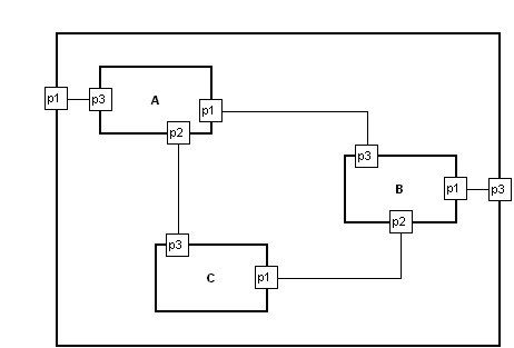 A, B, C and the enclosing unnamed object are all instances of the same component type. That type of component has three ports, p1-p3. Click the "Conn[ection]" button on the toolbar to start creating a relationship, click inside the edge of the first object where you want the port to appear, and you will be prompted to select one of the legal ports for that object. Similarly click inside the edge of the second object, and select the desired port. You can later move the port around the edge to a new position if desired, by clicking its role and then dragging the port. The ports will also move automatically where necessary, e.g. if the relationship would otherwise go across the middle of the object.
The model and metamodel can be downloaded as MovablePortExample.mec and imported into any MetaEdit+ 4.5 repository (e.g. log into the demo repository and open the Port example project, then choose Repository | Import).
It could be extended to have each component object show the ports that are not yet connected, either with a simple list in the text box in the object, or then as "fake" ports on the edge (with conditions so they disappear when that port is actually in use).
Edited by stevek - 10.Mar.2010 at 17:49 |
|
|
|
|
jkouwer
Major Contributor
Joined: 08.Mar.2010 Points: 22 |
Post Options
Thanks(0)
Quote Reply
Posted: 11.Mar.2010 at 00:20 |
|
Thanks for the example. It took me some time to find where you hid the ports, though

Still have lots of questions. And a headache...  meta-modeling, meta-meta-modeling is not easy, let alone learning a new tool. Ah, well, I'll try to get something up and running first. meta-modeling, meta-meta-modeling is not easy, let alone learning a new tool. Ah, well, I'll try to get something up and running first.
|
|
|
|
|
alev
Contributor 

Joined: 08.Oct.2010 Location: Arnhem, NL Points: 19 |
Post Options
Thanks(0)
Quote Reply
Posted: 20.Oct.2010 at 18:47 |
|
Steven, nice implementation of component modeling. However I looked into MovablePortExample.mec and could not find where ports p1-p3 are defined. Can you please explain?
|
|
|
|
|
janne
MetaCase

Joined: 25.Mar.2008 Points: 58 |
Post Options
Thanks(0)
Quote Reply
Posted: 21.Oct.2010 at 08:47 |
|
Hi,
MoveablePort (Port type) is defined in a Port Tool, having only one property Name. Then this port is linked to the Component (Object type) symbol (in symbol editor). This can be done via selecting first the Component's connectable and opening it's pop up menu and selecting Format. There are three ports denifed having names p1, p2 and p3, see enclosed picture.  Finally the PortRole (Role type) (small square in the end of the line) symbol is defined in the symbol editor. Chosen port name is fetched with generator script. |
|
|
|
|
Post Reply
|
Page 12> |
| Tweet |
| Forum Jump | Forum Permissions You cannot post new topics in this forum You cannot reply to topics in this forum You cannot delete your posts in this forum You cannot edit your posts in this forum You cannot create polls in this forum You cannot vote in polls in this forum |


 Topic Options